
We've got movement and it ain't us..!
Ok so the title does constitute a spoiler but it's also an unashamed tease!
With most of the signal wiring in and associated components mounted (throttle potentiometer, vacuum pump, motor controller etc) we turn our attention to the high voltage cabling.
Now let's be clear here, we're not racing for movement just for the sake of it. We're at the point where we need to validate the work (including vehicle integration effort) performed so far and the only way to do that is to connect some poweeerrr!
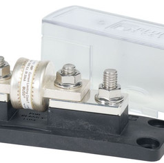
We start with our first crimp, always a momentous occasion in an EV build and quickly move on to our first connection from the gigantic 400amp fuse to the contactor.


The Turn On
In this build we will have two methods of disconnecting the battery. First up and the most common/normal will be via a contactor indirectly controlled by the cars ignition system or key and the motor controller. Interestingly the motor controller controls the power to itself so it decides, once a number of checks have been completed, if it's ok for the power to be connected.
The contactor is essentially a large relay which turns the high voltage supply off and on under normal conditions.


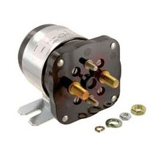


The second method (of connecting/disconnecting the power) is much more rudimentary and there's no other way to say it, it's a dirty great big and expensive switch to be used when the high voltage system is to be isolated during maintenance. We can also disconnect the power from within the cabin using a dirty big red kill switch. Safety is paramount!
Safety First!
There are other safety systems mandatory for all electric cars built or converted in Australia (e.g. Inertia switch) but we expect the requirements to change as adoption and awareness progresses. Therefore if you want more details on safety (Tip: you do!) I suggest you reference the Australian Design Rules (ADRs) or your local (and hopefully) friendly engineer when you're ready to build yourself.
The High Voltage cabling has a surprisingly large number of components to it which means a many joins, cuts and crimps too. The 2/0 (62mm2) gauge cable isn’t cheap either so it’s imperative we’re efficient and accurate with our cable runs to avoid wastage and dreaded rework. For every length, Con and I confer and double check the termination points before making use of our (immense ;-)) biceps, the snips and our crimping tool.
You’d be forgiven for thinking that the HV cabling simply involves connecting up the battery via a fuse and a switch to the controller. Not so, the best way to articulate this is through a diagram as I’m sure the pictures won’t tell the full story.
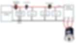
The diagram isn't meant to be something to build off so please don't critique it! There's details such as signal wiring, the 12v system and components such as the throttle potentiometer which I've not drawn to keep it simple.
Anyway, on with the rest of the HV cabling.. For its own protection, we mount the contactor switch in its own box and route cables to and from it. The routing of the cables and therefore component placement becomes obvious once we get started. The 3 phase cables (controller to the motor ) are both satidfying and aesthetically pleasing in equal measure.
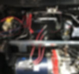
We then go grab the front battery box and batteries and mount for the last(?) time and connect up the negative to the controller and the positive to the hot side of the contactor.
So that should be it. There's power to the contactor, all signal wiring is connected, the batteries are charged what else is there to do? We perform our final checks time and again and discover there's nothing left to do but to turn the key!

We turn the key and... nothing. What have we missed? We start with diagnosing the controller. It tells us everything is just fine. No errors, but still no movement. It's got power and receiving throttle input as expected but then we see that the DRIVE = OFF in the diagnostics??
We realise that the pedal interlock, which prevents drive aways while still connected to a wallcharger, is enabled. We trace the issue to a microswitch on the throttle which we quickly resolve.
On a squeeze of the throttle we hear the faintest sound from under the bonnet. We squeeze it further and the turbine like sound of an induction motor is unmistakable. Take a look at the clip below. This was precisely the first turn of the wheels. I'll let the video and our unashamed excitement do the talking ;-).
But we're obviously far from finished!
Next time we put the wheels on the ground and go for a little drive and install the on-board charging solution!
